Optimizing Electronics Manufacturing with FR-4 Laminate Solutions

Dive into the transformative world of FR-4 material with our latest blog post, “Optimizing Electronics Manufacturing with FR-4 Laminate Solutions.” This comprehensive guide uncovers the unique properties of FR-4, from its flame retardancy and superior electrical insulation to its mechanical strength, explaining why it’s a staple in PCB manufacturing.
🎉🎉🎉Limited Time Offer Use code: QR4GNY08SHVR at checkout and enjoy a special discount on your entire order! 👉 FR4 fiberglass plastic
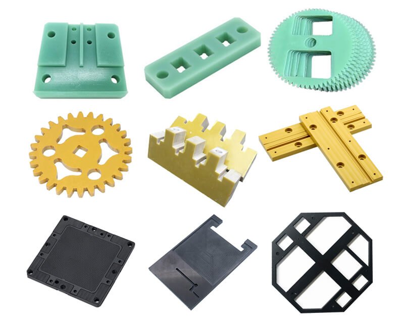
Learn about advanced fabrication techniques such as CNC machining and etching that ensure high precision and reliability. Discover how FR-4 compares to other materials like G-10 and polyimide, highlighting its cost-effectiveness and versatility. Explore the wide range of applications in consumer electronics, automotive, aerospace, and medical devices, showcasing FR-4’s adaptability to various industries.
Get expert tips on selecting the right FR-4 laminate by considering factors like thickness and thermal properties. Lastly, understand the economic and environmental benefits of FR-4, emphasizing its sustainability and compliance with safety regulations.
This post is your go-to resource for maximizing your electronics manufacturing efficiency with FR-4 laminate solutions.
Understanding the Unique Properties of FR-4 Material
Flame Retardancy and Safety
One of the standout characteristics of FR-4 material is its exceptional flame retardancy, compliant with the UL 94V-0 standard. This certification indicates that FR-4 can resist ignition and prevent the spread of flames, a critical feature for electronic devices that must adhere to stringent safety regulations. The flame retardant properties of FR-4 primarily come from the inclusion of brominated compounds, which significantly reduce fire hazards. This makes FR-4 a preferred choice for industries where safety is paramount, such as automotive and aerospace applications.
Electrical Insulation and Performance
FR-4 is renowned for its superior electrical insulation properties, which are crucial for maintaining signal integrity and preventing short circuits in electronic circuits. The high dielectric strength of FR-4 ensures that it can withstand high voltages without breaking down. Additionally, its stable dielectric constant over a wide range of frequencies makes it an ideal substrate for printed circuit boards (PCBs) used in communication devices, consumer electronics, and industrial equipment. The low dissipation factor of FR-4 minimizes energy loss, ensuring efficient performance of electronic components.
Mechanical Strength and Durability
The mechanical strength of FR-4 is another key attribute that contributes to its widespread use in electronics manufacturing. Composed of a woven fiberglass cloth embedded with epoxy resin, FR-4 provides excellent rigidity and durability. This combination allows FR-4 to support and protect sensitive electronic components from physical stress and environmental factors. Its resistance to mechanical wear and tear extends the lifespan of devices, making it a reliable choice for high-performance applications, including military and defense systems.
Moisture Resistance and Environmental Stability
Another critical property of FR-4 is its impressive moisture resistance, which ensures that it remains stable and functional even in humid environments. This is particularly important for electronics used in outdoor or variable conditions, where moisture can degrade materials and compromise performance. The low water absorption rate of FR-4, typically around 0.10%, ensures that the material maintains its mechanical and electrical properties over time, providing consistent reliability and stability for various applications.
Versatility in Electronics Manufacturing
FR-4 is versatile in its applications, making it suitable for a wide range of PCB configurations, from simple single-sided boards to complex multilayer designs. Its ability to accommodate various design requirements and its compatibility with standard PCB fabrication processes, such as drilling and etching, simplify manufacturing and reduce production costs. This versatility, coupled with its cost-effectiveness, makes FR-4 an attractive option for both prototyping and large-scale production in the electronics industry.
Comparative Advantages of FR-4
Compared to other materials like G-10 and polyimide, FR-4 offers a superior balance of cost-effectiveness, flame retardancy, and mechanical strength. While G-10 lacks the flame-retardant properties, FR-4’s enhanced safety features make it preferable for applications requiring higher fire resistance. Polyimide, though used in high-frequency and high-temperature applications, is generally more expensive. Thus, FR-4 stands out as a practical and efficient material choice for a broad spectrum of electronic devices and systems.
By understanding these unique properties, electronics manufacturers can leverage FR-4 to optimize their production processes, ensuring high-quality and reliable end products.

Advanced Fabrication Techniques for FR-4 Laminates
CNC Machining: Precision and Versatility
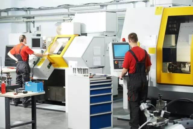
CNC machining plays a pivotal role in the fabrication of FR-4 laminates. This highly precise method involves computer-controlled machines that cut, drill, and shape FR-4 sheets to exact specifications. The accuracy of CNC machining ensures that every piece of FR-4 laminate meets the stringent requirements necessary for high-performance printed circuit boards (PCBs). The ability to produce complex geometries and intricate designs with tight tolerances enhances the reliability and functionality of PCBs used in various electronic applications.
Lamination Process: Creating Robust Structures
The lamination process is fundamental in the production of FR-4 laminates. This involves layering fiberglass cloth impregnated with epoxy resin, which is then pressed together under high pressure and heat. The heat causes the resin to flow and fill the gaps between the fiberglass layers, creating a solid and cohesive structure. This method not only provides mechanical strength but also ensures excellent electrical insulation properties. The lamination process is crucial for producing multilayer PCBs, which are essential for modern, high-density electronic devices.
Curing: Enhancing Material Properties
After the lamination process, the curing stage is essential to set and harden the epoxy resin, enhancing the mechanical and electrical properties of the FR-4 laminate. Curing involves maintaining the laminated materials at controlled temperatures to ensure the resin fully polymerizes. This step is vital for achieving the desired thermal stability and durability, making the laminates suitable for use in high-temperature environments. Proper curing ensures that the final product can withstand the stresses of manufacturing processes and operational conditions.
Etching: Defining Circuit Patterns
Etching is a critical process in PCB fabrication that involves removing unwanted copper from the laminated board to define the circuit pathways. After the drilling process, where holes for components and vias are created, the board undergoes chemical or laser etching to remove excess copper, leaving behind precise circuit patterns. This step is crucial for ensuring accurate electrical performance and signal integrity. The quality of the etching process directly impacts the reliability of the electronic devices in which the PCBs are used.
Batch Testing: Ensuring Quality and Consistency
To maintain high standards in PCB manufacturing, batch testing of FR-4 laminates is conducted to ensure each batch meets specific quality criteria. This testing includes evaluating mechanical strength, moisture resistance, and electrical properties. By rigorously testing the laminates, manufacturers can ensure that each board performs reliably in its intended application. Batch testing helps identify any defects early in the production process, reducing the risk of failures in the final electronic products.
Advancements in Thermoset Manufacturing
Recent advancements in thermoset manufacturing techniques have further enhanced the production of FR-4 laminates. These techniques involve using thermosetting polymers that, once cured, form a rigid and durable material with excellent thermal and mechanical properties. Innovations in resin formulations and processing methods have improved the performance characteristics of FR-4 laminates, making them more suitable for high-frequency and high-power applications.
By understanding and utilizing these advanced fabrication techniques, manufacturers can produce high-quality FR-4 laminates that meet the demanding requirements of modern electronics. From precise CNC machining to rigorous batch testing, each step in the production process plays a crucial role in ensuring the reliability and performance of FR-4-based PCBs.
Comparing FR-4 to Other PCB Materials
FR-4 vs. G-10: A Detailed Comparison
G-10 and FR-4 are both fiberglass-epoxy laminates, but they have distinct properties that make them suitable for different applications. G-10 was widely used before FR-4 became the industry standard. While both materials share similar mechanical strength and durability, FR-4 has a significant edge in flame retardancy. The addition of brominated compounds in FR-4 provides it with excellent fire-resistant properties, adhering to the UL 94V-0 standard, which G-10 lacks. This makes FR-4 the preferred choice in applications where fire safety is critical, such as in automotive and aerospace industries.
Cost-Effectiveness and Versatility
When it comes to cost-effectiveness, FR-4 outperforms G-10 due to its widespread availability and the economy of scale in its production. FR-4 is relatively inexpensive, making it an attractive option for mass production and cost-sensitive applications. Its versatility in handling various PCB configurations, from single-sided to multilayer boards, further enhances its value in electronics manufacturing. While G-10 might be used for specific industrial applications where flame retardancy is not a concern, FR-4 remains the go-to material for most electronics due to its balance of performance and cost.
FR-4 vs. Polyimide: High-Temperature Applications
Polyimide is another alternative to FR-4, particularly in high-temperature and high-frequency applications. Polyimide materials can withstand temperatures well above those that FR-4 can tolerate, making them ideal for applications such as aerospace and military electronics, where extreme conditions are common. Polyimide also offers better flexibility and chemical resistance, which is advantageous in dynamic or chemically harsh environments.
Electrical Properties and Performance
In terms of electrical properties, FR-4 provides excellent electrical insulation and a stable dielectric constant across a wide range of frequencies. This ensures minimal signal loss and interference, which is crucial for maintaining the integrity of high-speed circuits in communication devices and consumer electronics. Polyimide, on the other hand, has superior electrical properties at high frequencies, making it suitable for advanced applications such as RF and microwave circuits.
Mechanical Strength and Durability
Both FR-4 and G-10 offer robust mechanical strength, but FR-4 is generally preferred due to its better moisture resistance and flame-retardant properties. Polyimide also provides excellent mechanical strength but with added flexibility, which can be beneficial in applications requiring repeated bending or thermal cycling.
When to Use Alternatives
Despite the advantages of FR-4, there are scenarios where alternatives like G-10 and polyimide are more suitable. For example, in environments with extreme temperatures or where high-frequency performance is crucial, polyimide would be the better choice. Similarly, in industrial applications where flame retardancy is not a priority, G-10 might be preferred due to its adequate performance and potential cost benefits.
By understanding the strengths and limitations of each material, manufacturers can make informed decisions to optimize their PCB designs for specific applications, ensuring both performance and cost-efficiency.
Applications of FR-4 in Modern Electronics
Consumer Electronics: Powering Everyday Devices
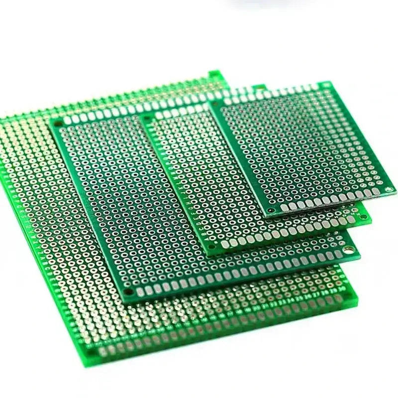
FR-4 is a cornerstone in the production of consumer electronics due to its reliable electrical insulation and mechanical strength. Devices such as smartphones, tablets, laptops, and televisions heavily rely on FR-4-based printed circuit boards (PCBs) for their operation. The material’s flame retardancy ensures safety in everyday use, preventing potential fire hazards caused by overheating or electrical faults. Furthermore, the cost-effectiveness of FR-4 makes it an ideal choice for mass production, keeping consumer electronics affordable while maintaining high quality and performance.
Automotive Industry: Enhancing Safety and Performance
In the automotive industry, FR-4 is used in a variety of critical applications, from control modules and sensors to infotainment systems. The material’s thermal stability and moisture resistance make it suitable for use in the harsh environments of vehicle interiors and engine compartments. FR-4’s ability to withstand high temperatures and resist moisture ensures that automotive electronics remain reliable under extreme conditions, contributing to the safety and efficiency of vehicles.
Aerospace Applications: Meeting High-Altitude Demands
Aerospace electronics demand materials that offer exceptional reliability and performance in extreme conditions. FR-4 is widely used in avionics, satellite communication systems, and other critical aerospace components. Its flame retardancy and mechanical strength provide robust performance, while its lightweight nature helps in reducing the overall weight of aerospace assemblies. The material’s ability to maintain electrical integrity at high altitudes and in variable temperatures makes it indispensable in this high-tech industry.
Medical Devices: Ensuring Precision and Reliability
FR-4 is also pivotal in the medical field, where reliability and precision are paramount. Medical devices such as diagnostic equipment, patient monitors, and imaging systems incorporate FR-4 PCBs due to their excellent electrical insulation and mechanical durability. The material’s biocompatibility and sterilizability make it suitable for use in both reusable and disposable medical devices. Its ability to perform consistently in various environments ensures that medical professionals can rely on these devices for accurate and dependable results.
Industrial Electronics: Durability in Harsh Conditions
In industrial settings, FR-4 is employed in control systems, power supplies, and automation equipment. The material’s resilience to mechanical stress and its robust electrical properties ensure that industrial electronics can withstand the rigors of manufacturing environments. FR-4’s resistance to chemicals and its ability to maintain performance in extreme temperatures make it ideal for industrial applications where reliability is critical to operational success.
Telecommunications: Supporting Global Connectivity
The telecommunications sector benefits greatly from FR-4’s stable dielectric properties and high-frequency performance. Components such as routers, switches, and modems utilize FR-4 PCBs to ensure efficient signal transmission and connectivity. The material’s flame retardancy and mechanical stability contribute to the longevity and safety of telecommunications infrastructure, supporting the backbone of global communication networks.
By leveraging the unique properties of FR-4, these industries can produce high-quality, reliable, and cost-effective electronic devices that meet the rigorous demands of modern technology.

Key Factors in Selecting the Right FR-4 Laminate
Considering Thickness for Optimal Performance
When selecting FR-4 laminate, one of the primary factors to consider is thickness. The thickness of the laminate can significantly impact the performance and durability of printed circuit boards (PCBs). Thicker laminates provide greater mechanical strength and rigidity, which is crucial for applications requiring robust structural support. For instance, in automotive and aerospace applications, thicker FR-4 laminates ensure that the PCB can withstand vibrations and mechanical stresses without compromising its integrity.
Conversely, thinner laminates are preferred in applications where space is at a premium, such as in consumer electronics and portable devices. Thin laminates help in reducing the overall weight and size of the device, making them ideal for compact and lightweight designs like smartphones and tablets. However, it’s essential to balance the thickness with the mechanical demands of the application to avoid issues like bending or warping.
Thermal Properties: Ensuring Stability Under Heat
The thermal properties of FR-4 laminates, particularly their glass transition temperature (TG), play a crucial role in determining their suitability for various applications. FR-4 materials come with different TG ratings, typically ranging from 115°C to 200°C. Higher TG materials can withstand elevated temperatures without losing their structural integrity, making them suitable for high-temperature environments such as automotive engine compartments or industrial settings.
For applications involving significant thermal cycling, such as aerospace electronics or high-power devices, selecting an FR-4 laminate with a high TG value is essential. This ensures that the laminate maintains its performance and reliability over prolonged exposure to high temperatures. Conversely, for applications with less stringent thermal requirements, standard TG FR-4 laminates can provide a cost-effective solution without compromising performance.
Dielectric Constant: Ensuring Electrical Performance
The dielectric constant (DK) of FR-4 laminate is another critical factor affecting its performance, especially in high-frequency applications. The DK value influences the laminate’s ability to store and transmit electrical energy. A stable and appropriate dielectric constant is essential for maintaining signal integrity and reducing signal loss or interference in high-speed circuits.
For applications such as communication devices, RF circuits, and high-frequency PCBs, choosing an FR-4 laminate with a consistent and suitable dielectric constant is vital. This ensures minimal distortion and efficient signal transmission. In contrast, for lower frequency applications or standard consumer electronics, the dielectric properties of standard FR-4 laminates are typically sufficient to meet performance requirements.
Moisture Resistance: Reliability in Humid Environments
Moisture resistance is a key property that ensures the longevity and reliability of FR-4 laminates in humid or variable environmental conditions. Laminates with low moisture absorption rates maintain their mechanical and electrical properties, reducing the risk of degradation over time. This makes moisture-resistant FR-4 laminates ideal for outdoor electronics, marine applications, and devices exposed to fluctuating humidity levels.
Compatibility with Assembly Processes
When selecting FR-4 laminates, it’s also important to consider their compatibility with various assembly processes such as soldering, drilling, and etching. Laminates that can withstand the thermal and mechanical stresses of these processes without degrading are essential for ensuring the quality and durability of the final PCB. This compatibility helps streamline manufacturing processes and reduces the risk of defects or failures during assembly.
By carefully considering these factors, manufacturers can select the most appropriate FR-4 laminate for their specific needs, ensuring optimal performance, reliability, and cost-effectiveness in their electronic applications.

Sustainability and Cost-Effectiveness of FR-4
Economic Benefits: Affordability and Availability
FR-4 is renowned for its economic advantages in the electronics manufacturing industry. One of its primary benefits is affordability. Compared to alternative materials like polyimide and ceramic substrates, FR-4 offers a cost-effective solution without compromising on quality or performance. This makes it an attractive choice for manufacturers aiming to produce high-quality printed circuit boards (PCBs) at lower costs, particularly for consumer electronics where pricing is highly competitive.
The widespread availability of FR-4 further enhances its economic appeal. Being a standard material in PCB manufacturing, FR-4 is readily available from numerous suppliers worldwide. This ease of access ensures that manufacturers can maintain a steady supply chain, reducing lead times and production delays. The high demand and production volume also contribute to its lower cost, making FR-4 a staple in the electronics industry.
Environmental Considerations: Recyclability and Safety Compliance
In addition to its economic benefits, FR-4 also addresses several important environmental considerations. One key aspect is its recyclability. While the recycling of PCBs presents challenges due to the complexity of materials involved, FR-4 laminates can be processed to recover valuable metals like copper. Advanced recycling techniques are being developed to improve the efficiency of reclaiming materials from FR-4-based PCBs, thereby reducing electronic waste and promoting sustainability.
Compliance with safety regulations is another critical factor that underscores the environmental benefits of FR-4. The material adheres to stringent safety standards, including the UL 94V-0 flame retardancy rating, which ensures that it resists ignition and prevents the spread of fire. This compliance not only enhances the safety of electronic devices but also aligns with regulatory requirements aimed at reducing environmental impact and ensuring the safe disposal of electronic products.
Flame Retardancy and Chemical Stability
FR-4‘s inherent flame retardancy contributes significantly to its environmental profile. The brominated compounds used in FR-4 laminates effectively inhibit combustion, reducing the risk of fire-related incidents. This property is particularly beneficial in applications where fire safety is paramount, such as in automotive, aerospace, and industrial electronics.
Additionally, FR-4 exhibits excellent chemical stability, making it resistant to moisture and various environmental conditions. This stability ensures that FR-4-based PCBs maintain their performance and durability over time, even in harsh operating environments. The reduced degradation rate of FR-4 components means fewer replacements and less waste, contributing to long-term sustainability.
Lifecycle and Durability
The durability of FR-4 extends the lifecycle of electronic products, which is a crucial factor in reducing environmental impact. Products that last longer do not need to be replaced as frequently, thereby minimizing waste. FR-4’s robust mechanical and electrical properties ensure that electronic devices can withstand the rigors of daily use and environmental stressors, further promoting sustainability by enhancing product longevity.
Regulatory and Industry Standards
Compliance with industry standards is essential for ensuring that FR-4 materials meet environmental and safety regulations. Organizations such as the National Electrical Manufacturers Association (NEMA) and regulatory bodies like RoHS (Restriction of Hazardous Substances) have established guidelines that FR-4 materials must adhere to. These standards help in reducing hazardous substances in electronic products, ensuring safer handling, and disposal practices.
By leveraging the economic and environmental benefits of FR-4, manufacturers can achieve a balance between cost-efficiency and sustainability, making it an ideal material choice for a wide range of electronic applications.

Common Questions and Answers about FR-4 Material and BeePlastic’s Customization Services
General Questions about FR-4 Material
1. What is FR-4 material and why is it used in PCB manufacturing?
Answer: FR-4 is a grade designation for glass-reinforced epoxy laminate material. It is known for its excellent electrical insulation, mechanical strength, moisture resistance, and flame retardancy. These properties make FR-4 an ideal substrate for printed circuit boards (PCBs) used in various electronic devices.
2. What are the key properties of FR-4 material?
Answer: The key properties of FR-4 material include high mechanical strength, good electrical insulation, low water absorption, and excellent flame retardancy (UL 94V-0 standard). Its thermal stability and resistance to environmental conditions also make it a preferred choice in electronics manufacturing.
3. How does FR-4 compare to other PCB materials like G-10 and polyimide?
Answer: FR-4 offers superior flame retardancy compared to G-10 and is more cost-effective than polyimide. While polyimide provides better performance in high-temperature and high-frequency applications, FR-4 is generally sufficient for most standard electronic devices due to its balanced properties and affordability.
4. What types of electronic devices commonly use FR-4 PCBs?
Answer: FR-4 PCBs are commonly used in consumer electronics (smartphones, laptops, televisions), automotive systems (control modules, sensors), aerospace components (avionics, communication systems), medical devices (diagnostic equipment, patient monitors), and industrial electronics (control systems, automation equipment).
5. How does the thickness of FR-4 laminates affect PCB performance?
Answer: The thickness of FR-4 laminates impacts the mechanical strength and thermal management of PCBs. Thicker laminates provide better support and durability for applications with high mechanical stress, while thinner laminates are used in compact devices to save space and reduce weight.
Questions about BeePlastic’s Customization Services
6. Can BeePlastic undertake any customization, including sample and batch customization?
Answer: Yes, BeePlastic can handle any type of customization, whether it’s for a single sample or a large batch. We work closely with clients to meet their specific requirements, ensuring that each project is tailored to their needs.
7. What file formats does BeePlastic accept for customization orders?
Answer: BeePlastic accepts a variety of file formats for customization, including PDF and CAD. This flexibility allows clients to submit their designs in the format that is most convenient for them.
8. Is there a minimum order quantity (MOQ) for customization at BeePlastic?
Answer: No, BeePlastic does not require a minimum order quantity. We cater to both small and large orders, providing the same level of service and attention to detail regardless of the order size.
9. How is the production cycle determined for customization orders at BeePlastic?
Answer: The production cycle at BeePlastic is determined based on the quantity of orders and the complexity of the process. We communicate with clients in real time to update them on the production progress, ensuring transparency and timely delivery.
10. Does BeePlastic provide samples, and who is responsible for the shipping costs?
Answer: Yes, BeePlastic provides samples free of charge. However, customers are responsible for covering the shipping costs. This allows clients to evaluate our materials and customization quality before placing larger orders.
By addressing these common questions, we aim to provide clear and comprehensive information about the benefits of FR-4 material and the customization services offered by BeePlastic.
Conclusion
FR-4 material is an indispensable component in modern electronics manufacturing, offering a unique combination of affordability, mechanical strength, and electrical insulation. Its wide range of applications across various industries—from consumer electronics to aerospace—demonstrates its versatility and reliability. At BeePlastic, we leverage these properties to provide customization services that meet the diverse needs of our clients. With no minimum order quantity and the ability to accept various file formats, we ensure that our customers receive tailored solutions with real-time production updates. By choosing BeePlastic, you benefit from our commitment to quality, sustainability, and customer satisfaction, making us your ideal partner in electronics manufacturing.
🎉🎉🎉Limited Time Offer Use code: QR4GNY08SHVR at checkout and enjoy a special discount on your entire order! 👉 FR4 fiberglass plastic

Don’t settle for less when you can have the best in FR-4 material customization. Fill out our contact form below to request your sample or custom batch. For a comprehensive look at what we offer, click here to explore our FR-4 epoxy glass fiber solutions.
-
Posted in
cost-effectiveness, dimensional stability, electrical properties, electronics manufacturing, FR-4 laminate, mechanical strength, multilayer circuit, optimization, PCB, performance